Noot / Erwt Notes
The Erwt and Noot are two small programmable robots I’m designing. The Erwt is a simple AVR-based Arduino-compatible through-hole kit, while the Noot is a surface-mount ARM-based design. More information on the Erwt is available at erwtbot.com.
Note #12 Saturday 12 November 2011
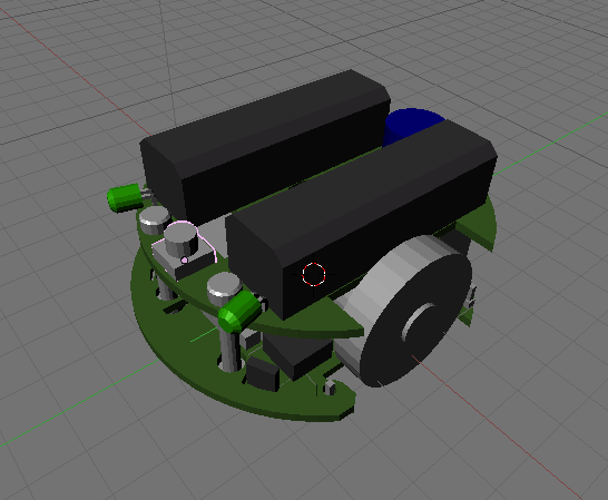
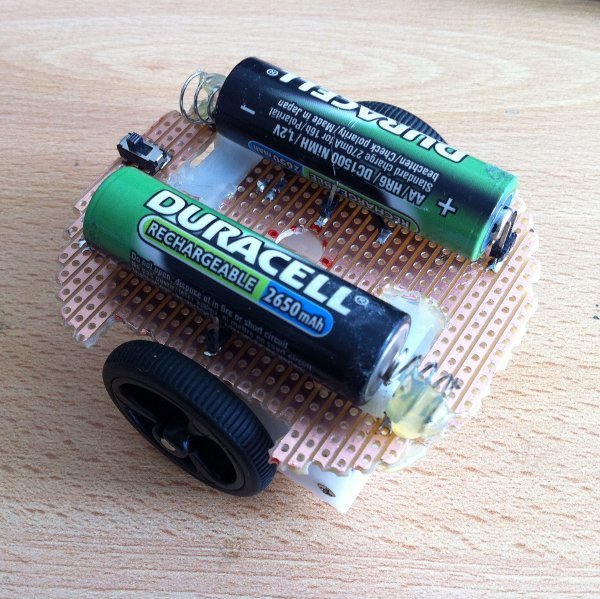
I’ve assembled the first Erwt and it all fits together rather well:
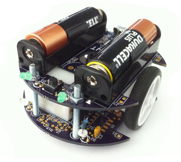
There are a few issues I’ll need to work out, so I’ll probably do another rev of the board soon.
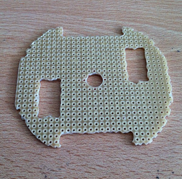
- The bumper PCB isn’t easily mountable in the way I’d hoped (on the front two bolts). I may need to rethink the design.
- The wheels are very close to the PCBs so I’ll move the motors out a little.
- There’s not enough space around the bolts for washers (which are needed to raise the bolt heads up enough to work as casters).
- The buzzer is too quiet with the double RC filter. I took one filter out and it’s a bit better, but is less crisp.
- The P2N2222’s I ordered have a different pinout from standard PN2222A’s (emitter-collector reversed).
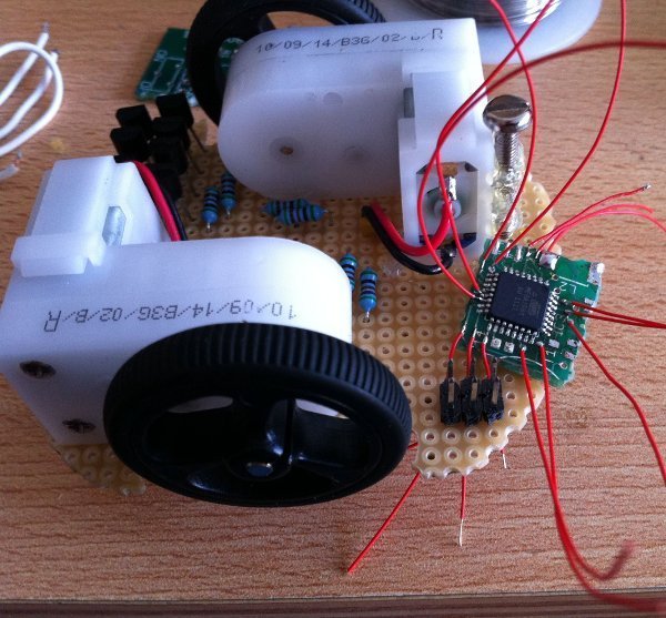
All relatively minor issues in the end, and all the IO (except the bumper) seems to work quite well. I have tested light following, line following and basic sound generation successfully. I’ve also written some basic libraries for the Arduino UI to support the various functionality. I’m now working on getting a kit ready for a friend to test:
The next steps are to fix up the various issues above, finalise the Arduino libraries, and finish the assembly instructions.
Note #11 Wednesday 02 November 2011
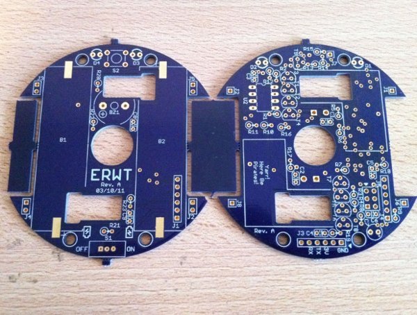
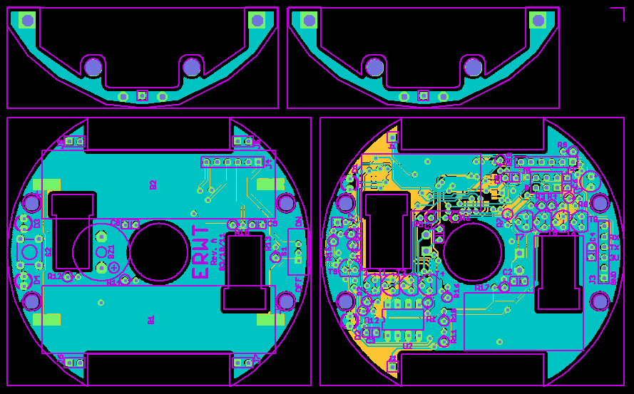
Boards arrived and they’re delightfully purple:
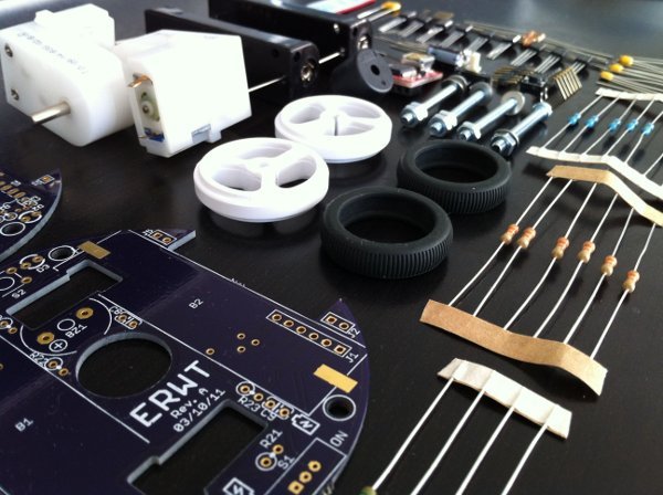
I also have all the parts (I hope) to assemble the 3 boards. I’ve been working on the assembly instructions and the tools to generate them:
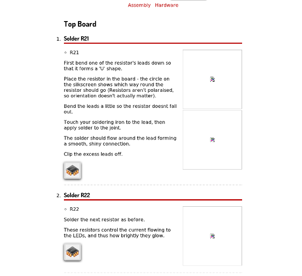
The chip icons expand to show little technical details about that specific assembly step.
Note #10 Monday 10 October 2011
Boards have been ordered, hopefully will get them in a couple weeks. I’ve been working on a site (erwtbot.com) in the meantime:
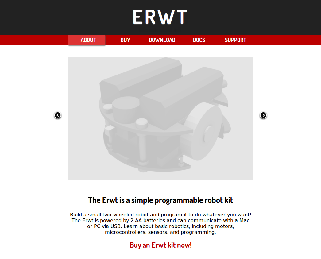
Lacking any real (reasonable-looking) photos of the robot, I have to make do with a boring render for now. Now I need to figure out how to make Paypal work in a somewhat user-friendly fashion. I’m also building a very simple WxWidgets UI for ErwtForth (similar to a stripped-down version of Foxtalk). At the moment the idea is a simple two-pane interface: a list of defined words and an interactive console.
Note #9 Sunday 02 October 2011
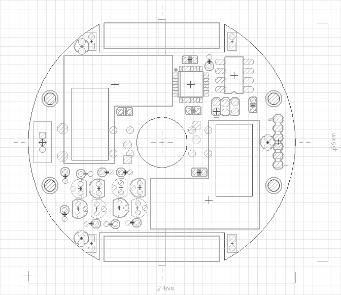
I reorganised the layout with the logic on the bottom board. This should make the kit steps simpler:
-
First, assemble the top board (batteries, switches, beeper, etc) and measure voltages.
-
Connect top and bottom boards via ribbon cable. Boards can be set next to each other at this stage.
-
Solder reset logic and serial connector, then connect to PC and test communication with ErwtForth (can beep buzzer and flash LEDs).
-
Solder H-Bridges and motors, test.
-
Solder remaining IO (light and reflectance sensors), test.
-
Bolt everything together.
Prototype Fab
I added a bumper PCB and was hoping to try out the DorkbotPDX PCB service, but I seem to have missed the October 3rd order. I’ll try again next week. If I’ve calculated correctly it should be around $100 for 3 full robots (a set of top, bottom and bumper).
Note #8 Friday 30 September 2011
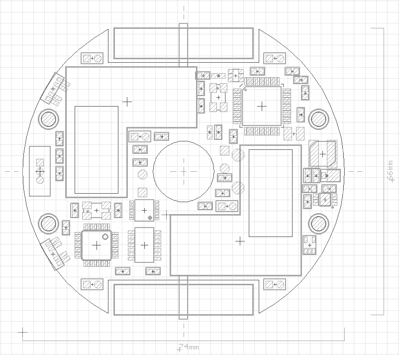
I finished up my first attempt at the layout:
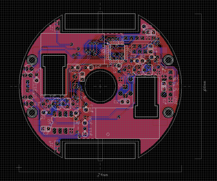
It was a surprisingly close fit. I’m not used to the annoying through-hole parts that occupy space on both sides of the board. I think I’m going to have to rework it though, as this layout has everything except the line reflectance sensors on the top PCB. This makes step-by-step assembly and testing (for the kit) annoying because the battery holders block soldering most of the components. I can probably move everything except the batteries, beeper, LEDs and pushbutton to the bottom PCB.
Bumper
I’ve also been playing around with ideas for the bump sensors. I’m considering making a bumper skirt mounted on the two front bolts with something squishy (washers maybe?). The bumper would have a wire to ground and two through-hole plated holes that fitted around (but not touching) two header pins on the left and right. Pushing against the bumper would, in theory, touch the pin to the plating, closing the circuit. Have to see if that’ll actually work.
Repository
I’ve committed the current schematic and layout, as well as the blender file, to my Bitbucket repository.
Note #7 Sunday 25 September 2011
My very shaky knowledge of analog electronics means that transistors and I do not get along well. It was most concerning when my H-bridge didn’t actually work as the sim had predicted:
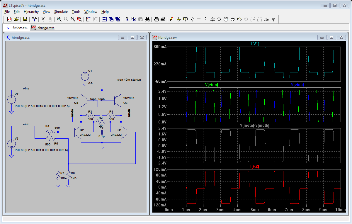
It’s a sim. It’s 100% accurate! Right? At least the digital ones are (… sometimes). I pouted a bit then rebuilt the circuit and it worked fine. Damn transistors. I am getting about 300mV drop from battery to motor, which might be an issue with NiMHs. I also discovered that, of course, there is a way to let out the magic smoke with this bridge, or at least trigger the getting-really-hot state. Both inputs high.
AVR
I also started wiring up the AVR:
It seems my AVR Dragon would only program the chip at 3.3V. That isn’t really a problem though, as I’ll only do initial programming bootloader programming via ISP. Got the motors running with some test code. No luck communicating via serial yet.
Serial Interface
My original plan was to use an FTDI Cable for serial interfacing. But thinking about it more, it might be a reasonable idea to build a tiny interface board around an ATMega8U2 as used in the Arduino. It would be about the same price (Ignoring assembly costs for now), but it would make a nice starting point for future FT2232 / JTAG replacement work. Then I could replace the whole FT2232 section on the Noot with an ATMega and crystal. The Versaloon Code has a simple JTAG implementation that’d be worth looking at.
Encoding
Spent a while puzzling over potential wheel encoding solutions. I really think it’ll be necessary if you want to Logo turtle stuff. Options to investigate:
-
Detecting motor flux with a hall-effect sensor on the side of the motor?
-
Mounting a magnet on some shaft and hall sensing that.
-
Back-EMF, which would need a better H-bridge
-
Some sort of breakbeam / reflectance thing on the wheels.
If all else fails I can just measure battery voltage and guestimate motor speed (awfully).
Note #6 Saturday 24 September 2011
Transistors and veroboard for prototype arrived and I hacked out a quick test board:
Some old battery holders, some header and a lot of hot glue later:
It runs around quite happily with NiMH AAs which is good to know (~2.4V). Must be careful about the eventual battery holders though, as the motors could get in the way of the pins (might need to make them non-symmetric, sigh). Added the transistor H-Bridges which work OK, but probably need the resistor values tweaked. I thought I could hook up the AVR by just soldering thin wire to the pins but that appears to be too much fiddly-work. I’m go to see if can chop the AVR footprint off an old Cogbot board tomorrow and use that as a base.
Note #5 Wednesday 21 September 2011
Noot CPU
The low-cost Cortex-M3 cpus seem to be dominated by NXP (LPC13x) and ST (STM32x). While I’ve used TI’s Stellaris for all my Pindakaas development, in theory any M3 with a JTAG port will suffice. This immediately disqualifies the LPCs, as they only have Serial DebugWire (SWD) interfaces. OpenOCD (which Pindakaas uses to interface with the CPU) currently only supports pure JTAG, so that leaves me the STMs.
The most suitable STM seems to be STM32F100 series which comes in a 48 pin LQFP with 8KB RAM and up to 128KB flash. This is a quick layout test:
The boost converter is on the right, between the two bolts. The top right is FT2232 + related USB / JTAG stuff. Bottom left is the ARM and H-Bridge. I’ve added two of the reflectance sensors I used on the Foxbot as well, but I found those really annoying to mount so it’d probably be worth trying to find something better. USB connector, pushbutton, beeper (need to find an SMD one as the pins for the Foxbot one are annoying to fit on this board) and LEDs are on the other side.
SWD
I should investigate what’d be needed for SWD though, as I assume most low-pin-count ARMs will move towards it. There was some discussion about OpenOCDs support, so I assume it’ll eventually arrive. Also, I should look at a replacement for the FT2232, as it’s a rather expensive part for just JTAG interface. I’m sure a small USB-enabled ARM or AVR could provide equivalent functionality for much cheaper (Like the Arduino guys did with the USB AVR to replace their FT232). But thats a cost optimisation, so it can wait for now.
Note #4 Tuesday 20 September 2011
Received the motors and they’re adorably tiny:
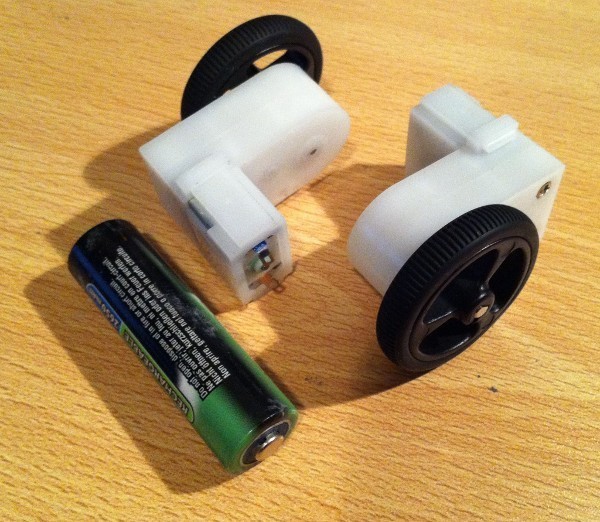
If only they had encoders, then they’d be perfect (I wonder if you can do rubbish encoding with a hall-effect sensors stuck to the side of a motor).
The motors run just fine from 1V up to 5V. At 3V, the no-load current is 80mA, and the stall current is 500mA.
Erwt CPU and Layout
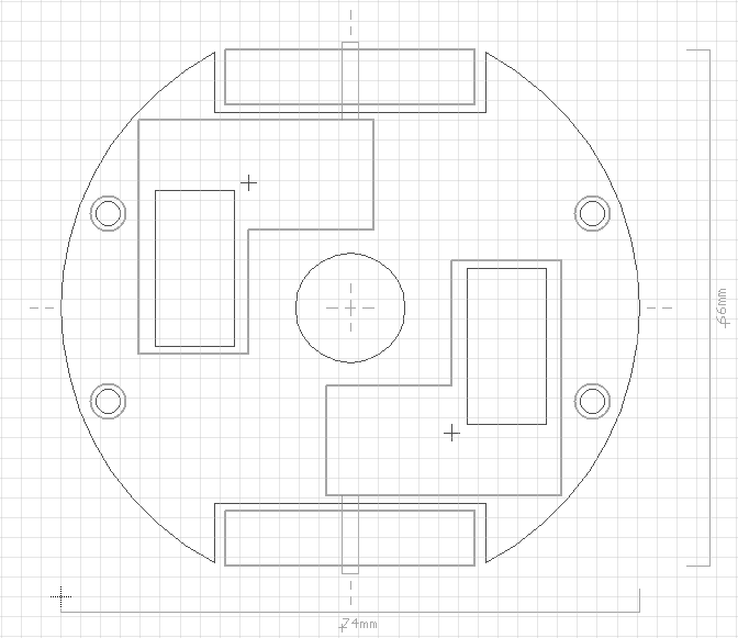
I’ve decide on an ATMega168 for my Erwt development. I think it’s going to be too hard to fit any through hole AVR on the board with all the headers and other necessary parts. The ATMega would be the only SMT part and it could be pre-soldered in the case of a kit. The layout would look something like this:
The 8 pin DIP is an I2C EEPROM for program storage. The 2x3 pin header is the AVR ISP while the 1x6 pin is for serial (I must decide on a standard for that). The 4x 2 pin headers would be to pass signals down to the bottom PCB (which could have line following sensors).
I’ve also ordered some veroboard and components to make a prototype Erwt board.
ErwtForth
I’ve started work on a very simple Forth environment in python which talks to a tiny C VM:
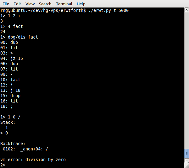
Its a disgrace to Forths (all the immediate words are implemented in Python), but it at least lets me play around on the AVR (I’ve compiled the VM for my old Cogbot board, which also has an ATMega168).
Note #3 Saturday 17 September 2011
The 2xAA supply makes for some interesting power choices. If I work on the assumption of Alkalines, that’ll give a workable supply range of about 2-3V. Most microcontrollers will run down to 1.8V so that shouldn’t be a problem, but a most H-bridges are 3V+. This is especially true for the common through hole part: the L293D / SN754410.
Pololu claims 800mA @ 4.5V stall current for the motors, so in theory I’d need to be able to supply max 1.5A.
As a result, my two choices seem to be:
-
Boost the battery voltage up with a buck converter and use that to supply the motors and logic. The Pololu 3pi Robot does this.
-
Build an H-bridge from discrete parts. The BEAM guys do this, and for small motors it shouldn’t be a problem.
Noot
I think the deciding factor for the Noot is the FT2232 which doesn’t operate below 3.3V, requiring boosting. This shouldn’t be much of an issue actually, as I can use a relatively cheap buck converter to get me something in the 5V range, then regulate that back down to 3.3V with an LDO. There are a lot of compact 3V to 5V boost converters that switch at MHz frequencies (meaning tiny external inductor and cap) for Li-ion to USB conversion. I’ll use either the TB6112FNG (used on the Foxbot) or the LB1836M dual H-bridge ICs.
Erwt
Unfortunately, boosting doesn’t appear to be an option for the Erwt, as all the through-hole converters are either low current (won’t be able to drive the motors) or low frequency (huge inductors). However, you can do a super-simple 4 transistor bridge (from an old BEAM design):
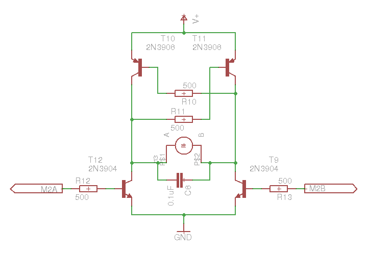
This will be able to handle the 3V supply and 800mA stall (with the right transistors). The crossover design means I only need 2 drive lines per bridge, and its impossible to drive the bridge with magic-purple-smoke-releasing-inputs.
I’ve ordered a pair of motors and wheels from pololu as well as a LB1836M for testing.
Note #2 Sunday 11 September 2011
Noot / Erwt
I’m going to split this robot into two different designs. Both will have the same motors and physical dimensions. The Noot will be “high density SMT” with ARM+FTDI and Pindakaas-powered. The Erwt will be through-hole (as much as possible, so it can be assembled as a kit) with an AVR running Forth.
Layout Test
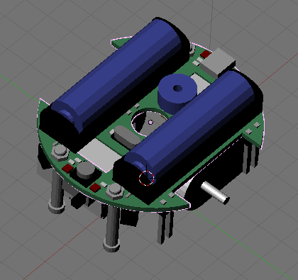
I’ve done a quick layout test to check how the motors will fit:
I think I’ll just sandwich the motors between two PCBs, then the 4 bolts will also act as casters. Doesn’t look like they have any convenient mounting holes. The space between the motors is enough for at most a 2cm hole for a pen. The batteries would then mount on the opposite side of the board (this render is for the Noot, and doesn’t show the other PCB):
There’s definitely enough space for a few small TQFPs, which means the Noot design should work, but it’ll probably be quite tight with only through hole parts (for the Erwt). I think I’d leave USB off in the Erwt design (just use a FTDI cable), but it still needs to fit at least a CPU and a H-Bridge. 16pin DIPs will just fit between the motor and the bolt, so that limits me to a smaller ATTiny.
Note #1 Tuesday 06 September 2011
I’m going to try keep a log of the Noot design process as a reference for why I made unwise-in-hindsight decisions.
The Noot is effectively a Foxbot v2. The goal is a small, cheap, easy to produce robot, avoiding the USB hassles I had with the original Foxbot. It should be easy to write code on and provide some method for hardware expansion
CPU / Language
My original plan was to try make something minimal - maybe a 4-8KB ATTiny - that would be programmed in Forth (the interactivity/REPL is important). But given the size-constraints imposed by the motors, it seems the only feasable route would be SMT components, at which point a small ARM seemed like a better choice than an AVR. I can also fit the FT2232 for a JTAG-USB interface (like the Stellaris dev boards), so I’ll be able to run Pindakaas. The FT2232 avoids any USB difficulty as there are drivers available for all the platforms (often without needing to download anything extra). Actually, I might build a separate robot with the same motors, but using an 8-14 pin ATTiny, just to see how it’d work. I must investigate the ARM choices.
Motors
The design is based around the Pololu plastic gearmotors and 32x7mm wheels. These are both cheaper and smaller than the metal gearmotors and wheel combo used on the Foxbot. I’ll lose the ability to encodered-feedback on the motors, but I never used that on the Foxbot anyway. I’m going to order a pair of motors and wheels for measurement and testing. The L-shape gearbox is convenient for the physical layout as when arranged in a mirror configuration, it leaves space in the centre for a possible pen, while still being smaller than the Foxbot.
Power
The motor+wheel combination results in a bot of about ~75mm diameter, which gives an internal square of 53mm to a side. AA’s are 14.5x50.5 and AAA’s are 10.5x44.5. That means 3xAA or 4xAAA. But it’d be nice to leave space in the middle for a pen to do turtle-style drawing. That reduces it to 2xAA or 2xAAA. Which gives 2-3V for the main supply.